Connecting an Amstrad EME-231 compatible 3" drive to an Amiga
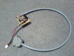
Ever wanted to connect an Amstrad 3” disk drive to your Amiga for emulator usage or disk dumping? The circuit presented here can be used to interface double sided, double density 3” disk drives like the Amstrad EME-231.
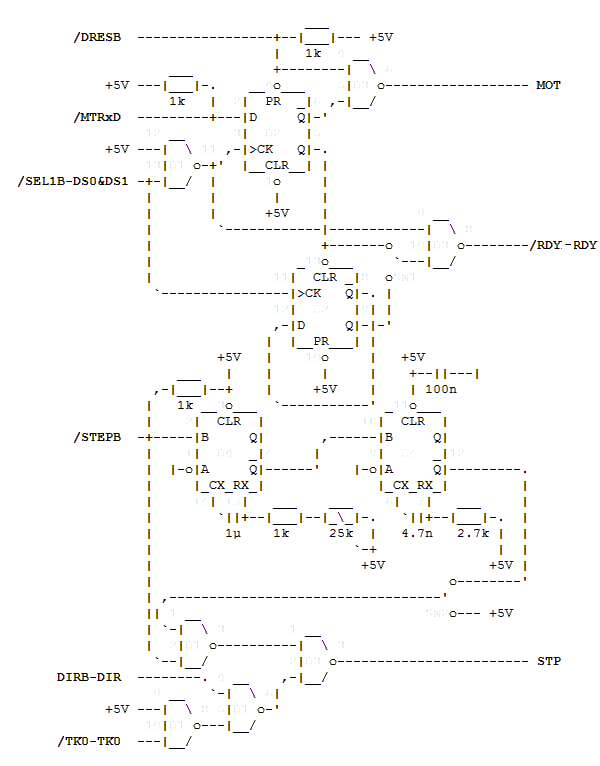
The schematic features a switchable drive id via SW1 (0×00000000 for Amiga or 0×55555555 for 37422D2S identification) and a switchable double step mode for reading 40 track disks via SW2. When in double step mode, the delay for the extra pulse can be adjusted between 0.32ms and 8.32ms - it is described by t=0.32RC(1+0.7/R), whereas C=1µF and 1k≤R≤26k in this schematic. As most 3” disk drives aren’t hard-stopped at track 0, the circuit also inhibits step pulses going to the drive when the head is at track zero and is being told to step out (like trackdisk.device does if TDU_PublicUnit.tdu_PubFlags is set to TDPF_NOCLICK).
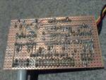
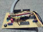
The circuit makes use of four TTL chips: 74LS00 (U1), 74LS74 (U2), 74LS38 (U3) and 74LS123 (U4). Ground has to be connected to pin 7 on U1, U2, U3 and to pin 8 on U4 while the supply voltage (+5V) must be connected to pin 14 on U1, U2, U3 and to pin 16 on U4. The remaining signals not shown in the schematic are simply passed through: /DKRD to RD, /SIDEB to SS, /WPRO to WP, /DKWEB to WG, /DKWDB to WD and /INDEX to IDX.
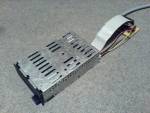
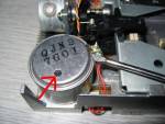 Note about drive speed: It seems that there is quite a variation on drive motor speed between each drive. For dumping purposes the drive must be spinning at 300 RPM. The SPS dump tool will confirm your drive speed for us, but if it’s not 300rpm then the drive will need to be adjusted. This is done using a program that will report the drive speed to you, such as DriveSpeed and adjusting the Pot-Resistor on the drive motor, as pictured, THIS MUST BE DONE IN STAGES WHILE THE COMPUTER/DRIVE IS OFF! or else the Pot-Resistor can short out.
This adaptor is also compatible with Single Sided 40-Track variants of 3” drives. In this scenario the ID switch should be set to the 40 track position, but the stepping switch MUST be set to SINGLE STEP ONLY else damage will occur to the drive!
Circuit Diagram
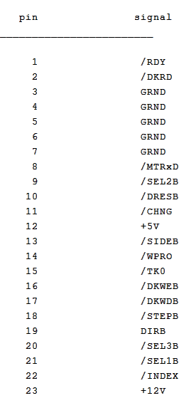
Amiga External Drive Port Pinout
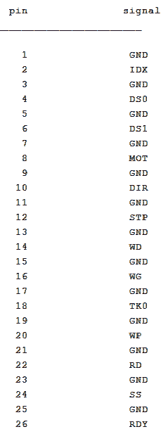
Amstrad EME-231 Drive Pinout
Disclaimer
SPS takes no responsibility for any damage to drives or connected equipment caused by following this guide. Undertaking any instructions from this document is done so entirely at your own risk, and while SPS has made vast amounts of effort to ensure this information is correct, we cannot guarantee that no damage will occur as a direct or indirect result of the instructions given.
![[logo]](/lib/tpl/sps/layout/header-logo.png)
![[motto]](/lib/tpl/sps/layout/header-motto.png)

